

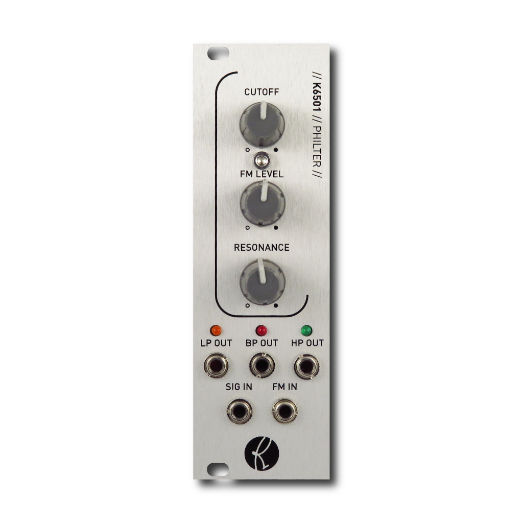
K6501 PHILTER
User Manual
Download a PDF version of the manual here: K6501-philter-manual.pdf
Note that PDF manuals are automatically generated from webpages. Links and embedded media will not be accessible. For the full experience visit our website: www.kilpatrickaudio.com
Introduction
The amazing success of the PHENOL Patchable Analog Synthesizer has definitely created a demand for some of the PHENOL aspects in the Eurorack world. By popular demand we have released the K6501 PHILTER which is based closely on the filters found in PHENOL.
Setup
The K6501 PHILTER requires only +12V and -12V. Make sure you use a good power supply that is not overloaded. The voltages should measure as close to +12V and -12V as possible.
To get something happening right away, just patch an oscillator signal into the SIG IN jack and take the output from the LP OUT jack. Vary the CUTOFF control and check out the sound.
Jacks and Controls
Audio Inputs and Outputs
The SIG IN jack is the audio input for the module. This accepts a +/-5V (10V peak to peak) signal. Note that with high resonance the outputs may produce up to +/-10V. PHILTER can produce three outputs at the same time:
- LP OUT - Low-pass output - sounds at and below the cutoff frequency
- BP OUT - Band-pass output - sounds centred around the cutoff frequency
- HP OUT - High-pass output - sounds at or above the cutoff frequency
Each audio output jack has an LED which will light when strong signals are coming out of the jack.
Tuning
The CUTOFF control affects the resonant frequency of the filter. When resonating, the cutoff frequency setting will determine which sounds are accentuated. Beyond this frequency the other signals will either be passed unchanged, or rolled off depending on which output you use.
The FM IN jack and FM LEVEL control are used to control the cutoff frequency from a control voltage. The FM IN jack responds exponentially to control voltages from approx. -5V to +5V. Negative and positive voltages will add or subtract from the front panel CUTOFF control setting accordingly.
Resonance
The RESONANCE control affects how much signals around the cutoff frequency will be accentuated. PHILTER is intentionally design not to self-oscillate, since filter are not really as good as oscillators in this regard. Instead, a built-in resonance limiter circuit allows very high resonance settings without oscillation. This produces very strong and "fat" sounds even though PHILTER is a simple two-pole design. This is what makes PHILTER sound so punchy and musical!
Audio and Control Voltages
Kilpatrick Audio strives to make products with the most convenient and universal voltage standards possible. We believe in the approach that everything should be able to patch into everything and therefore all our modules are based around the most universal -5V to +5V range. Pulses and gates are 0V off / +5V on. Pitch voltages range from -5V to +5V and use the standardized 1 volt per octave scaling. Audio, LFO and envelope voltages also range from -5V to +5V. This gives the absolute best compatibility between different module types. Our non-Eurorack products also follow this same system.
Whenever you see an offset control on one of our modules that is mixed with a CV input, there is an easy way to picture how it works. Simply imagine the offset control setting the value of the particular function with no input signal. (or a 0V input signal) Putting a CV signal into the corresponding input jack will simply add or subtract from this offset setting. Some inputs have attenuator controls (we call them LEVEL) that allow you to scale the input signal. This simply scales down the input signal before it can affect the internal circuitry.
Need Help?
Feel free to contact us for more information, to report errors or unclear sections, or to request specific information be added to this manual.