

PHENOL
User Manual
Download a PDF version of the manual here: phenol-manual.pdf
Note that PDF manuals are automatically generated from webpages. Links and embedded media will not be accessible. For the full experience visit our website: www.kilpatrickaudio.com
Manual Sections
Introduction
Welcome to the wonderful world of patchable analog synthesis! PHENOL is inspired by modular synthesizers, but designed to be compact and affordable. Whether you already have a big modular system, or whether you are just getting into the fun of patchable synthesis, PHENOL has a lot to offer you. It's not just a small version of a modular synth. The entire design is conceived from the ground up to be a fun and flexible musical instrument with an unprecedented feature set. In many cases you will probably find yourself turning to PHENOL as your "go-to" synth for many projects. I hope you have as much fun using PHENOL as we did in creating it!
This manual is just a starting point to give you some tips on the various features and details that might not be obvious. When possible we also encourage you to view the videos that we have made to accompany this manual. But for those of you who prefer to read manuals cover to cover, or have them as handy reference material, this is for you!
Like any webpage, you should consider this page to be a work in progress. One of the reasons we no longer offer PDF or printed manuals is because we want to expand and correct things as needed. Also, we want to be able to link you to videos and sound files where necessary, which is only possible in this medium.
Precautions
PHENOL is designed to be rugged and reliable, but there are some things that we must say just in case. We take no responsibility for improper use or abuse. Although we want you to have many years of great fun with PHENOL, it's up to you to take care of your system.
- Keep PHENOL dry: This includes rain, beer, water and coffee.
- Only use the included power supply: If you need to replace your power supply, contact Kilpatrick Audio for help. Your PHENOL could be damaged by the wrong power supply.
- Connect Ground Correctly: When patching to other equipment, you MUST connect a ground between
the two systems BEFORE patching. Never leave patch cables connected between systems without a proper
ground or both ends of the connection may be damaged. You can do this one of two ways:
- Use the banana ground jack on the rear panel to ground to another banana system.
- Use an audio jack such as an EXT IN jack to connect to a grounded jack on a minijack or 1/4" system.
- Protect the Front Panel Controls: When storing or transporting PHENOL make sure the front panel controls are not damaged. They should last a long time if properly cared for. Do not place objects on top of PHENOL or put the synth unprotected into a bag.
- Do not open PHENOL: We can't prevent you from doing what you want with PHENOL, but any poking around inside is entirely at your own risk. All calibration adjustments can be made without removing the bottom cover.
- Be careful when adjusting trim pots: Oscillators and the MIDI to CV converter are adjusted through holes in the bottom panel. Use an appropriately sized flat screwdriver and take care not to poke other nearby components. Put PHENOL on a soft surface such as foam or bubble wrap while adjusting.
When using the USB MIDI connection, you might introduce a ground loop hum in your system. The DIN MIDI jack is electrically isolated and therefore may make a better connection in some setups. Grounding is tricky and this is purposely why PHENOL ships with only a 2-wire power supply. Consult with an experienced audio tech if you need more assistance with studio grounding.
Important Notes
As we get questions or discover things about that are noteworthy, we will post them here.
- Proper Gain Settings - PHENOL is by design fairly raw sounding. This is by design as we want you to experience analog synthesis in its truest form. Like any audio equipment, having the correct gain settings throughout the signal path will result in the best sound. The mixer signal LEDs light to indicate nominal levels. If you don't see them lighting, consider increasing the gain throughout your patch.
- Envelope in OSC Mode - Sometimes when changing envelope modes, if the envelope generator is already running it may not behave as intended. Turn the mode off and back on again to reset it.
- Sequencer Mode - It is reported that sometimes the sequencer mode may stop responding after recording. We are investigating this issue and will provide an update
- Ground Loops - Whenever a computer is introduced into a music setup there is the potential for noise to be added to audio signals. This is why MIDI was designed to be optically isolated. USB cannot be as easily isolated so there is a potential of introducing ground loops when using USB. Consult with an audio professional for grounding and cabling advice if you experience trouble in your setup.
- Need more help? - Do you have a question or comment about any features / functions of PHENOL? Contact Us
Basic Synthesizer Concepts
Unlike a synth with presets, like a keyboard synth that has your favourite piano sound, nothing in PHENOL is patched for you. If you just want to dial through sounds, then PHENOL is probably not going to be what you're looking for. But PHENOL offers something different by not making any decisions for you in advance. Even though preset synths can have lots of programmable options, the basic signal path is usually determined by the designer. Plus, who wants to menu dive to just change one setting? Boring! PHENOL takes a different approach by giving you the building blocks required to create and explore sound. You can build up a sound from scratch and evolve it... get your recorder running because even the exploration can often end up in an interesting piece of audio!
When people talk about connecting a modular synth, they usually talk about the patch. Indeed modern preset synths and software often still use this terminology, which originates with modular synths that use patch cords. The patch usually refers to not only the patch cord connections, but also the settings of the various controls. Indeed both the actual wiring and the control settings have a huge impact on what you hear. And many modules (or sections as we call them on PHENOL) have different modes of operation, which can impact how the controls and connections respond.
There are two main ways to think about sound creation with PHENOL:
- As a synth controlled by a keyboard
- As a synth that just "does its own thing"
Both ways are completely valid. If you're looking to create a cool bass or lead sound to use on a track, the first method is probably what you want. Build up a typical signal path for a synth, and then tweak and add modulation sources to create just the sound you want. However if you want to create a drone, or sound scape or just a really cool patch that evolves and has its own life, forgetting about the keyboard might be the best way to start. One of the main advantages of a patchable synth like PHENOL compared with most MIDI or VST preset synths is that you don't have to press a key on your keyboard to make a sound! Once you break free from this "hold down a key before turning a knob" way of thinking, you will realize how much more sound exists! Even just breaking away from the idea of equal tempered notes is very liberating, and is probably where most early electronic musicians' heads were before keyboards came along and forced electronic musicians to become a piano players.
Synthesizer Building Blocks
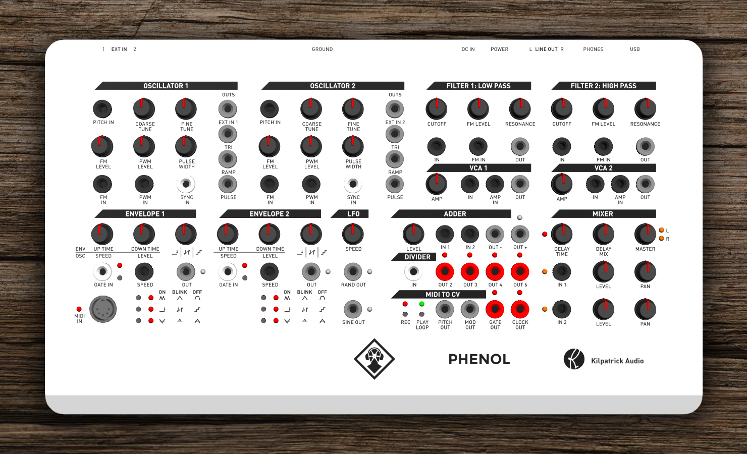
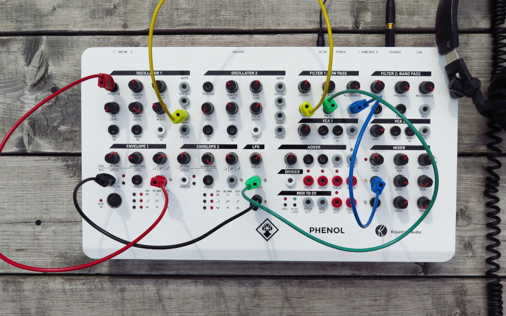
PHENOL panel - Click for a larger view.
PHENOL contains most of the fundamental building blocks that are needed for basic sound synthesis. We'll dedicate a section for each, but here is the basic overview:
- Oscillators - The oscillators, or voltage-controlled oscillators (VCOs) are the primary source of sound in PHENOL. There are two oscillators which are the same. They produce triangle, ramp (sawtooth) and pulse waves. The oscillators also have an output for external audio sources.
- Filters - The filters, or voltages-controlled filters (VCFs) allow the frequency content of an audio signal to be changed. PHENOL has one low-pass filter and one high-pass filter.
- VCAs - The voltage-controlled amplifiers (VCAs) allow the level of a signal to be adjusted manually or under voltage control. VCAs are normally used to adjust the volume of a sound signal, but they can be used for other purposes as well.
- Envelopes - The envelope generators make low-frequency signals such as volume / pitch envelopes, low frequency modulation signals and stepped voltages which can be used in many different ways.
- LFO - The low frequency oscillator (LFO) is a very simple way to make some changing voltages. It can create low frequency sine waves as well as random voltages and white noise.
- Adder - The adder is a useful section that can be used to actively mix two signals together, change the level of the signals, and flip them over.
- Divider - The divider is used to divide pulses and gates and outputs four different versions at slower rates. This can be used for all kinds of interesting purposes.
- MIDI to CV - The MIDI to control voltage (CV) converter is the interface between PHENOL and other digital music gear like MIDI keyboards, synthesizers and computers. The MIDI to CV converter also contains a mini sequencer.
- Mixer - The mixer is the final step for audio signals in PHENOL before they head out to headphones or speakers. The mixer also contains a digital delay which can add effects to the audio signal.
Control Voltages and Patch Cords
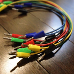
Probably the most obvious difference between PHENOL and a preset synth or plugin you may have used is the presence of patch cords. PHENOL uses standard banana patch cords because they are rugged, stackable, and look and feel great. All signals travel through the same type of cords which means that there are no rules as to what goes into what.
To patch effectively and get the most out of your system you should understand the basics of how the control voltages and audio signals work. This will give you a solid foundation in analog and modular synthesis, and the concepts apply to most patchable systems.
Types of Signals by Function
When people talk about CVs (control voltages) they are generally referring to one of two types of signals, which in the case of PHENOL are interchangeable:
- Control Signals - Usually low frequency signals like pitch, gate, and modulating signals used for shaping and affecting a patch.
- Audio Signals - The actual audio signals generated by oscillators and shaped with filters, VCAs and so on.
The difference between these types of signals can be a bit blurry. In fact some systems try to keep them separate by using different kinds of voltages or connectors, but we feel as though this is severely limiting, thus PHENOL and the Kilpatrick Format modular system use the same voltages and connectors for audio and control signals. The only real distinctions are the frequency of the signals, and their intended use. But even this is rather vague depending on the patch.
Voltages in PHENOL
PHENOL (and also the Kilpatrick Format system on which PHENOL is based) uses two main types of voltage ranges: audio and CV signals that range from about -5V to +5V, and gate or pulse signals which can be either 0V or +5V. There are four colours of jacks used to differentiate between the two types of signals, and the input / output direction:
- CV / Audio Output - GRAY - Control voltages and audio signals come out of gray jacks. These are normally in the range of -5V to +5V.
- CV / Audio Input - BLACK - Control voltages and audio signals go into black jacks. These can handle signals in the range of about -10V to +10V, but are designed for the -5V to +5V range used by the outputs.
- Pulse and Gate Output - RED - Pulse, gate and clock outputs and various other digital type of signals come out of red jacks. These are nominally +5V when on, and 0V when off.
- Pulse and Gate Inputs - WHITE - Pulse, gate and clock inputs go into white jacks. These detect any voltage greater than about +1V. Some inputs like oscillator sync inputs require fast changing signals like pulse waves. Any range of voltages can be put into these jacks, making them useful even with CV and audio signals.
The Importance of Bipolar Signals
One of the unique aspects of Kilpatrick Audio synths is the nearly universal use of bipolar control signals. Other than pulses and gates, all control voltages are bipolar. This means that the all control voltages range from -5V to +5V, with 0V being the nominal voltage when a cable is disconnected. Some synths either use only unipolar voltages (i.e. 0V to +10V) or use a combination of unipolar and bipolar voltages, which is often confusing and creates incompatibilities between modules.
Imagine for a moment that you set up an oscillator using the tuning controls to operate at a specific frequency. By inputting a pitch voltage that ranges from -1V to +1V, the pitch of the oscillator will vary up and down by 1 octave in either direction.
Envelope signals on PHENOL also operate in a bipolar way. This means that when an envelope is at rest (not running) it sits at -5V. When triggered, the voltage ramps up to +5V and then back down again. This uses the full range of available voltages. If a filter cutoff frequency is swept up and down by this voltage, the frequency will vary above and below the nominal setting. If you want to check the filter without any envelope attached, simply pull the cable out and tune it manually. The cutoff control will already be in the middle of the range, so hearing what's going on and adjusting it is easy.
People familiar with other modular systems might find it strange that all voltages, even envelopes are bipolar. But there are almost no situations where this is a disadvantage. Circuit designs almost always work better through the centre of their designed ranges, and having unlimited choices for patching makes synthesis a whole lot more fun.
The point of this section is to always think of CV and audio signals as signals that vary above and below a nominal point. Also, it is important to remember that signal inputs respond to CVs by adding or subtracting from the particular control setting. If you keep these things in mind while experimenting with PHENOL, it should make a whole lot more sense.
Using your PHENOL Safely
There are not too many rules when it comes to how to treat your PHENOL. Although we try our best to make rugged products, is a precision electronic instrument and so be careful not to drop PHENOL or get it wet. Also, make sure that you never use abrasive or harsh cleaning products that could damage the panel.
As for actually plugging in an using PHENOL, only use the included power supply which outputs 24VDC at 500mA. If you need to use a different power supply please contact us before plugging it in. Damage caused by using the wrong power supply could be expensive to repair. If the input voltage to PHENOL is too low PHENOL protects itself by not powering on. If you see the mixer output LEDs and delay time LED blinking, this indicates a power supply problem.
When patching, there are no limitations on where you can patch signals within PHENOL. It is permissible to stack 2-3 outputs together max. This will create a passive mixing function which is acceptable. Do not put more than 3 outputs together, and never patch the MIDI to CV converter PITCH OUT or MOD OUT together with any other output. If you need to mix these signals with another output signal use the ADDER section to mix them together properly.
Patching to External Equipment
When patching PHENOL to other analog synths, it is vitally important that PHENOL be grounded to the other equipment at all times while patch cables are attached between the systems. Stray voltages on equipment can reach dangerous levels which could damage equipment. A ground jack on the back panel can be used to ground another banana system. Otherwise, you can use an audio cable plugged into one of the audio jacks to do this. The EXT IN jacks are useful for this purpose. Plug an audio cable from the EXT IN jack into a grounded connection on the other system, and you should then be safe to patch across. Banana cables can be made or purchased from Kilpatrick Audio to connect with minijack or 1/4" equipment. Keep in mind that the voltage ranges might be different on different systems, so check with the manufacturer of the other equipment first. PHENOL can safely handle voltages betwen -10V and +10V without damage.
Blocks in Detail
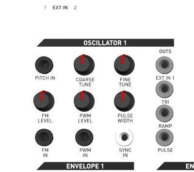
Oscillators
There are two voltage-controlled oscillators (VCOs) on PHENOL which are identical. Each uses a traditional style sawtooth core and has a temperature-compensated exponential converter for stable pitch control. Triangle, ramp (sawtooth) and pulse waveforms are available all at the same time. The practical frequency of operation is from a few Hz up to more than 18kHz.
The COARSE TUNE and FINE TUNE controls are used to set the frequency of the oscillator.
The PITCH IN jack is factory-calibrated to respond to a 1V/octave control voltage. It can be used with the MIDI to CV converter to play notes from a keyboard or other MIDI device. The FM IN jack also responds exponentially but the sensitivity can be adjusted by the FM LEVEL control. Both PITCH IN and FM IN jacks will allow the frequency of the oscillator to be varied up and down from the current COARSE and FINE tune setting.
The PULSE output jack makes pulse waves which have adjustable width. The PULSE WIDTH control adjusts the width. The PWM IN allows the pulse width to be adjusted by a voltage.
The SYNC IN jack is used to hard sync the oscillator to another source. It works best if fast transitioning waves like pulse or sawtooth waves be used.
Note on stability and calibration: Each oscillator has two trimmer controls accessible through the bottom cover. One is used for the V/octave tracking of the PITCH IN jack, and the other is used to set the triangle symmetry. Before assessing or adjusting the calibration make sure the PHENOL has warmed up for at least one hour. Do not remove the bottom cover when making calibration adjustments.
PHENOL contains two external input jacks. Although they are not really part of the oscillators, their outputs are presented along with the oscillator outputs. Two 1/4" jacks on the rear panel accept line level signals. The signals are internally buffered and amplified to the levels needed by PHENOL. This can be used to process external audio sources through PHENOL. If you want to use a guitar or other high-impedance signal you should use a preamp before sending the signal into PHENOL.
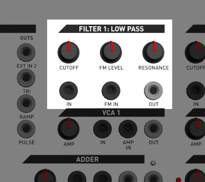
Filters
PHENOL has two filters: low pass and band pass. The low pass has extreme resonance and is great for making fat sounds and picking out specific harmonics in a signal. The band pass design started out as a high pass, but evolved into band pass during development. Early models may be marked "high pass" but the filter circuit has not changed. It is most useful for cutting out low frequency signals and accentuating different ranges of high frequencies from waveforms like ramp and pulse. Both filters are designed for high resonance without oscillation and employ a special resonance limiter circuit developed by Andrew Kilpatrick specifically for PHENOL. The filters are a big part of what makes PHENOL an instrument with a sound all its own.
An audio signal is passed in through the IN jack. You can take a signal directly from an oscillator to test it out. Output comes from the OUT jack. Pass this into the MIXER to hear the effect right away.
Turning the CUTOFF control will affect the cutoff frequency of the filter. The resonance control affects how the frequencies peak around the cutoff point and can be used to make the cutoff frequency more prominent.
The FM IN is used to control the cutoff frequency with a voltage. The FM LEVEL control affects the sensitivity of the FM IN jack. Control voltage signals passed to the FM IN will cause the frequency to rise and fall from the CUTOFF setting, as the voltage goes up and down.
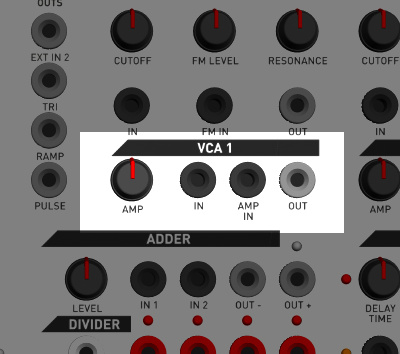
Voltage-Controlled Amplifiers (VCAs)
There are two VCAs on PHENOL. The voltage-controlled amplifiers (VCAs) are used to adjust the level of audio or control voltages signals. This can be done manually using the AMP control, or by a voltage input into the AMP IN jack.
Input an audio or control voltage signal into the IN jack and take the output from the OUT jack. Adjust the AMP control manually. Inputting a voltage into the AMP IN jack will allow the level of the signal to be increased or decreased as the voltage goes up and down.
Notes about responses, voltages: The VCAs respond exponentially to control voltages because they are primarily designed for use with audio signals. But the signal path is DC-coupled which means that you can pass control voltages and lower frequency signals through the VCAs as well. You can use this to adjust modulations like vibrato depth under voltage control, for instance.
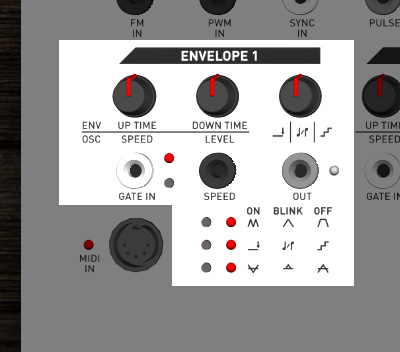
Envelopes
There are two envelope generators on PHENOL. These are more accurately described as envelope / oscillators because they have a number of ways they can be used to generate either envelopes, commonly used to fade notes up and down, or making low-frequency oscillations which have many different uses.
There are three buttons and three LEDs near the bottom of the section which are used to adjust the mode of operation, the function of the third control, and the polarity of the output signal.
Note about button settings: The modes selected by the three small buttons on each envelope section are not saved during power off. The PHENOL experience is designed to be immediate and easy to learn, therefore PHENOL starts up fresh each time.
Modes
There are two main modes of operation for the envelope sections: envelope mode and oscillator mode. When running in envelope mode the output will ramp up and down according to a gate signal. In oscillator mode the output will ramp up and down continuously, which can be used to generate varying voltages for different purposes.
Notice that the first two controls have two sets of labels each. The top labels are marked with: ENV which means that in envelope mode the functions of the controls are UP TIME and DOWN TIME respectively. In oscillator mode (marked as OSC) the controls are used as SPEED and LEVEL respectively.
Envelope Mode
You can select attach / hold / release (AHR) envelope mode by pressing the top mode button until the LED is not lit. In this mode a gate signal input into the GATE IN jack will cause the envelope to go up and down. Normally this would be patched into the GATE OUT jack on the MIDI to CV converter, but you can input any signal here. The envelope can also be triggered manually by pressing the button next to the GATE IN jack.
When triggered, the envelope will ramp up to the maximum level in a time set by the UP TIME control. The output will stay at the top until the gate is released. The output will then fall to the minimum value at a speed set by the DOWN TIME control.
You can also use the envelope generator in attack / release (AR) mode by pressing the top mode button until the LED blinks. In this mode the envelope will ramp all the way up and down no matter how long or short the gate signal is.
Oscillator Mode
You can select oscillator mode by pressing the top mode button until the LED is lit. In this mode the output will go up and down with rate determined by the SPEED control. The output level is adjustable by using the LEVEL control. By default the oscillator will be turned on when entering the mode. This can be used if you want a continuous output. If you want to start and stop the oscillator you can use the GATE IN jack or press the gate button to cause momentary output.
Third Control Mode
The third control has three icons underneath: a line with an arrow, some music notes, and some steps. These three modes are selected by the second mode button as indicated on the adjacent LED. These modes work regardless of whether you are using envelope or oscillator mode.
- Steps - When the mode LED is not lit, steps mode is selected. In this mode the third control adjusts the output smoothness. You can select the number of steps in the output from 2, (lowest voltage, highest voltage) all the way up to a perfectly smooth wave.
- Gate Delay - When the mode LED is lit, gate delay mode is selected. The third control can be used to adjust how long the module takes to respond after a gate signal is input. Use this for instance with two envelopes to fade up a note with one, and then add modulation after a time delay.
- Scale Quantize - When the mode LED is blinking, scale quantize mode is selected. In this mode the output signal will be quantized to scale notes. The third control is used to select one of 16 different scale choices. Various arpeggio combinations are provided.
They are named as follows:
- 5ths
- 5ths and 7ths
- major
- major 7th down
- minor
- minor 7th
- minor 7th down
- minor alternating
- major alternating
- minor alternating 7ths
- major alternating 7ths
- clusters 1
- clusters 2
- jumping
- blues
- leading
Note about scale quantize mode: Scales are factory set in a custom control unit and cannot be changed by the end-user.
Output Mode
The third mode button adjusts the output mode. There are three choices which work with all other combinations of settings:
- Normal - When the mode LED is not lit, normal mode is selected. The envelope / oscillator output will go from the lowest voltage to the highest voltage and back down again. When the envelope or oscillator is not running, the lowest voltage will be output.
- Inverted - When the mode LED is lit, inverted mode is selected. The envelope / oscillator output is the same as in normal mode, except inverted. When the envelope ramps up the output will actually go down instead. When the envelope or oscillator is not running, the highest voltage is output.
- Absolute Value - When the mode LED is blinking, absolute value mode is selected. In this mode the output will be centred (around 0V) when not running. When the envelope / oscillator is running, the output will only go up, and the range of output voltage will be reduced by half. This mode is useful for making gated trills and other effects with oscillators.
SPEED Jack
The SPEED jack allows the current speed of whatever is happening to be scaled up or down by a voltage. This works for both envelope and oscillator modes and can be used to modulate the up and down time of the envelope, or the rate of the oscillator.
Note about output calibration: The outputs of the envelopes cannot be calibrated. They are engineered by design to be 1V/octave, but may vary due to part tolerances. If using for pitch, try using the FM IN on the oscillators to allow the scale span to be adjusted easily.
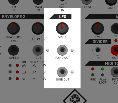
Low Frequency Oscillator (LFO)
The low frequency oscillator (LFO) is a very simple utility section used to make several useful signals. The SINE OUT jack generates low frequency sine wave signals. The RAND OUT jack makes random stepped waveforms. The SPEED control sets the speed of both outputs.
If the SPEED control is turned up to the maximum setting, the RAND OUT generates high frequency white noise. This can be filtered or used as a source of audio.
Note about outputs: Both the SINE and RAND outputs are digitally generated. The bandwidth and resolution of both signals is limited by design. These limitations add to the raw character of PHENOL.
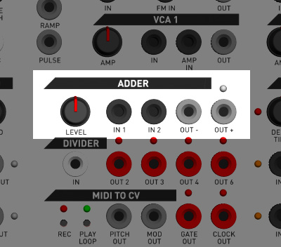
Adder
The adder is a useful section which performs mixing, scaling and inverting of audio or control voltage signals. The IN 1 and IN 2 jacks are internally mixed using an active mixer. The LEVEL control adjusts the output signal from 0-200% of the input.
The OUT + jack provides an in-phase signal, and the OUT - jack provides an inverted signal. The LED shows the in-phase signal.
Note that by adding too much gain it is possible to cause clipping of the output, or overdriving whatever is connected to the output of the adder. This might be what you want, but if not, just turn down the LEVEL control.
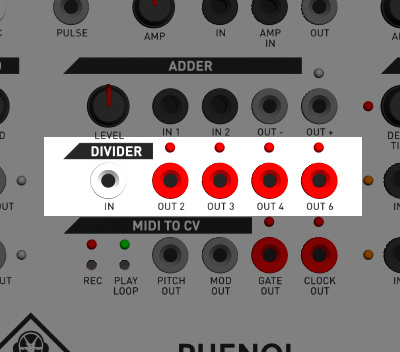
Divider
The divider allows gates and pulses to be divided to create signals which are slower but related in time. This is most useful for dividing LFOs or clock signals to create outputs which change another parameter at some divisor of the main clock.
For instance, if a signal is taken from the OUT 2 jack, it will toggle on or off every time the input rises.
To use, input a gate or pulse signal into the IN jack. The outputs will divide the input signal by 2, 3, 4, and 6 all at the same time. Keep in mind that a signal cannot be divided equally into 3, so the on and off time of the output will not be equal.
There is a magical feature of the divider module related to resetting. If a MIDI clock start message is received by PHENOL, the divider outputs will be reset. This allows a repeatable performance when driving PHENOL from a computer or other sequencer.
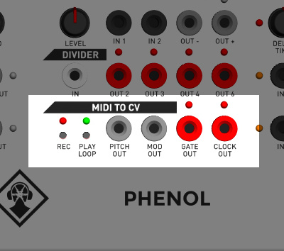
MIDI to CV Converter and Mini Sequencer
The MIDI to CV converter allows MIDI devices such as keyboards, as well as computers to control PHENOL. You can input MIDI via the DIN jack in the lower left corner of the panel, or via the USB connector on the rear panel. This section also contains a small sequencer which can record and playback short sequences.
Note about settings and sequences: Settings such as the pitch bend range, and the sequence recorded in the sequencer are not saved during power off. The PHENOL experience is designed to be immediate and easy to learn, therefore PHENOL starts up fresh each time.
MIDI to CV Converter
MIDI signals can be input via the DIN jack or the USB connection. The USB will show up as a class-compliant USB MIDI device on your computer. Both inputs can receive messages at the same time.
There are no settings for the MIDI converter channel or output mapping. It always responds on MIDI channel 1. Note messages will be converted to voltages on the PITCH OUT and GATE OUT jacks using monophonic last-note priority. The modulation wheel will produce voltages on the MOD OUT jack. Clock signals received will produce pulses on the CLOCK OUT jack. Note that the clock output produces 1/16th note pulses, despite MIDI clock running at a higher rate.
Pitch bend messages will work in the normal way when notes are played. Program change commands can be sent to PHENOL to adjust the amount of bend. Programs 1-12 set the bend range from 1-12 semitones.
MIDI Clock Handling
Some keyboards generate MIDI start, continue and stop messages when using the internal sequencer or arpeggiator. PHENOL will respond accordingly by starting and stopping the CLOCK OUT signal. Sometimes you might want it to continue generating clock pulses despite your keyboard's sequencer being stopped. We made an enhanced version of the PHENOL firmware (ver. 1.26 released in August 2018) which allows MIDI clock stop messages to be ignored. See below for usage instructions.
To ignore MIDI clock stop messages from a MIDI source:
- Turn off PHENOL with the rear power button
- Turn on PHENOL with the rear power button
- Within 5 seconds, press and hold the REC button for at least 1 second.
- The REC and PLAY LEDs with flash briefly indicating that MIDI clock stop messages will be ignored.
- To restore the default behaviour of responding to MIDI clock stop, simply power cycle your PHENOL.
Note that the setting is not saved on power down. You must disable it each time you turn on PHENOL.
Sequencer
The mini sequencer can record and playback MIDI sequences from a keyboard. You can use the sequencer in step sequencer mode or real-time recording mode.
To use step sequencer mode, press the REC button. The record LED will blink indicating that the sequencer is ready to accept notes. Play a sequence of notes. (more than 500 notes can be recorded) To insert a rest, use the damper pedal (CC #64). To stop recording press REC or PLAY. To play the sequence back once, press the PLAY LOOP button. To play the sequence back in a loop, press and hold the PLAY LOOP button, or hold it down while the sequence is already playing.
To use real-time recording mode, press record and play to start recording. The record and play LEDs will both begin flashing. Recording starts when the first event is received. In real-time recording mode you can record pitch bend messages as well as notes.
While the sequence is playing you can transpose the playback by pressing notes on your keyboard. If a sequence is looping you can stop the loop using the damper pedal.
To change the tempo, send CC #16 from a knob on your keyboard. When using the internal clock (the default) this affects the absolute step sequencer tempo, and the relative tempo of the real-time recording. When the internal clock is used the start of a sequence is indicated on the CLOCK OUT jack.
When using an external MIDI clock, CC #16 affects the clock divider setting so that you can adjust the playback speed relative to the MIDI clock. A higher setting means more dividing, so the playback will appear slower as you turn up the divider control more.
Note: When using an external MIDI clock it is necessary to send a clock of at least 10BPM.
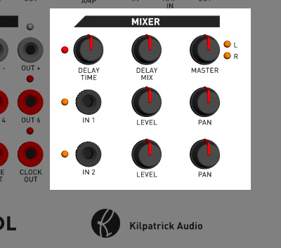
Mixer
The mixer is a two input digital mixer designed for maximum audio quality in a tiny form factor. The IN 1 and IN 2 jacks allow signals to be input to the mixer. An LED beside each input shows the relative signal level. Each input channel has a LEVEL and PAN adjustment which can be used to affect the level and position within the stereo mix.
The MASTER control affects the main output level. The mixer outputs a line level and headphone level signal on the rear panel. Both can be used at the same time to feed other equipment. The line outputs are unbalanced and designed to be connected to an input impedance of 10K or more. Do not connect to mic inputs with phantom power or the unit could be damaged.
The DELAY TIME and DELAY MIX controls are used to add delay / echo to the main mix. The delay time can be adjusted from about 1-300ms. The DELAY TIME LED will blink showing the speed of the delay. The DELAY MIX is a combination of mix and feedback in a single control. Turning up the control to about mid way will give approx. 100% delayed signal vs. dry signal. As the control is increased further the amount of delay feedback is increased, allowing the sound to be built-up.
Note that the delay uses a lo-fi delay line using a lossy companding algorithm. You may experience some gritty sounds due to the quantization noise in the algorithm. This is part of the PHENOL sound and is not a defect. If you want pristine delays and reverb, an external effects processor is a better choice.
Oscillator Calibration
Each PHENOL is carefully calibrated at Kilpatrick Audio before being sent to you. However at some point you may want to adjust the calibration either for optimal performance or to more closely track other CV sources.
STOP! Do you really want to do this? Your PHENOL is probably fine, so please think twice before poking around in the calibration holes. Kilpatrick Audio offers FREE calibration and check-out of all products. We have technical service depots in Europe and North America to help you.
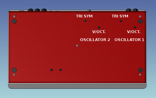
The image above shows PHENOL from the rear side. Note the orientation of the rear panel connectors. Each oscillator has trim pots for triangle symmetry and volts / octave adjustments. These pots are 25-turn units and require a quality small flat adjustment screwdriver. Note the pair of trim pots associated with the oscillator you wish to tune.
Adjusting the Triangle Symmetry
View the triangle output on an oscilloscope or listen to it without any effects turned on. Adjust the trim pot until the triangle peaks line up on both halves of the cycle, or until you hear the least amount of high frequency content in the signal. A small amount of irregularity is normal even in a perfectly tuned unit.
Adjusting the Scale Span (V/octave)
Power on the unit for at least 30 minutes before adjusting the scale span.
Feed a calibrated MIDI to CV converter or a desired CV source into the PITCH IN jack on the oscillator you wish to calibrate. Use your ear or a guitar tuner connected to a line out jack to measure the pitch. Adjust the CV source in octave steps and aim for the best match over a wide span of 6-8 octaves. Turning the trim pot clockwise will increase the size of an octave, and counter-clockwise will decrease it. Check the tuning at each octave and aim for the closest match across the range of interest.
Because all analog oscillators and MIDI to CV converter DACs have some amount of error it will not be possible to obtain perfect tuning across the entire musical frequency range.
Need Help?
Feel free to contact us for more information, to report errors or unclear sections, or to request specific information be added to this manual.